
Mini Lathe Page
Last Updated: 12/10/2014
On This Page
Mini Lathe Page
Last Updated: 12/10/2014
On This Page
![]()
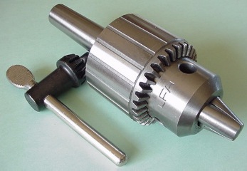
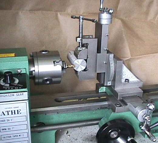
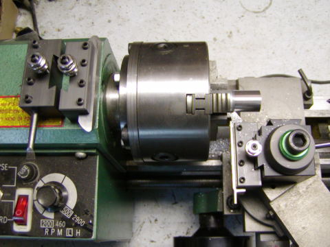
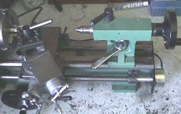
MINI LATHE.... I have a Mini Lathe on my reloading bench. The picture shows the lathe with a TOS 4" 3-Jaw chuck instead of the stock 3" 3-Jaw chuck. It has a 7" swing and is 10" between centers and only takes up 24" of space on the reloading bench. It is small, but had a 0.808" hole through the headstock and would do some barrel work on smaller diameter barrels. I purchased a 13/16" reamer and have bored the headstock out to 0.8125" so it will now accept a Contender carbine bull barrel. I have been having a lot of fun (and expense) getting tooled up as a Mini Machine Shop. I made a brass collet that will hold the base of a 243 Win case and the lathe will sure spin a 243 brass with ease. I made an aluminum muzzle brake for my Contender carbine and it works very well after a bit of redesign (see my Shooting Page). It makes the recoil of the 17 Mach IV about like a 22 LR. I have made a lot of improvements on the Mini Lathe. Below is a list of required accessories and lathe improvements to make it all work. As I make improvements and find new reloading things to do with the lathe, I will post them here on this new page. This is the Bethel Island Machine & Fussing section of my web page.
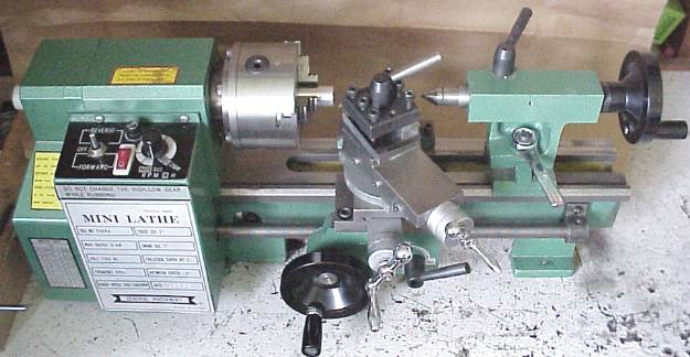
HF 7x10 Mini Lathe.
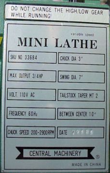
The Name Plate.
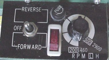
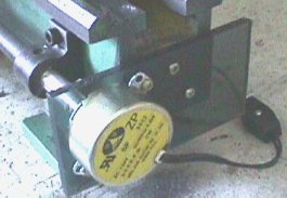
The Control Panel.
|
Mini Lathe Specifications from Harbor Freight.
|
People have been asking where I got the lathe. I purchased it from Harbor
Freight Tools. It is made in China and the word Precision, in the title,
is used rather loosely! Frank Hoose's Mini-Lathe.com![]() is about the best web page out there on the Mini Lathe. A
is about the best web page out there on the Mini Lathe. A ![]() 7
x 10 Mini Lathe Owner's Group has been formed. The group exchanges info and
tips on improving their lathes. Check in, read the messages, and join the group
if you are interested in contributing.
7
x 10 Mini Lathe Owner's Group has been formed. The group exchanges info and
tips on improving their lathes. Check in, read the messages, and join the group
if you are interested in contributing.
 The MicroLux
7x14 High-Precision Heavy-Duty Miniature Lathe is now available from Micro-Mark
but is expensive and has more features and optional accessories.
The MicroLux
7x14 High-Precision Heavy-Duty Miniature Lathe is now available from Micro-Mark
but is expensive and has more features and optional accessories.
MINI LATHE NECESSARY EXTRAS.... Here are some accessories that you will need to make your lathe work like it should. First, you will need three Machinery Catalogs that have most everything you can imagine and the prices are reasonable. You can go to their web site and I also included their phone number:
Below are some tools that are essential for making a Mini Lathe a complete tool. First, you will need a 1" Micrometer and a 6" Dial Caliper, but mine are old and since I haven't tried any of the new ones listed in the catalogs, I dont want to make any recommendations on items I have not personally used.
KBC Tools & Machinery 1998-1999 Catalog:
Grizzly Industrial Metalworking 1999 Catalog:
Harbor Freight Tools Catalog:
 USE
QUALITY METALS FOR YOUR PROJECTS.... You can order brass, aluminum, mild
steel and other alloy rods and bars in small or large quantities from OnlineMetals.com.
Spending a lot of time turning a project out of an unknown material and have it
fail is merely machining practice. If you start with materials of know quality,
your finished projects will have the best chance of being high quality. I have
included a Metal Mechanical Properties File, material.txt
for over 1000 structural materials. The mechanical properties are in English
Units. These are the data that I have use for years for material modeling in
thousands of Finite Element calculations.
USE
QUALITY METALS FOR YOUR PROJECTS.... You can order brass, aluminum, mild
steel and other alloy rods and bars in small or large quantities from OnlineMetals.com.
Spending a lot of time turning a project out of an unknown material and have it
fail is merely machining practice. If you start with materials of know quality,
your finished projects will have the best chance of being high quality. I have
included a Metal Mechanical Properties File, material.txt
for over 1000 structural materials. The mechanical properties are in English
Units. These are the data that I have use for years for material modeling in
thousands of Finite Element calculations.
LATHE IMPROVEMENTS.... I'm having a lot of fun improving the new lathe. I am using it for reloading. But, so far I am mainly in the tool making and improvement phase. A lathe is a marvelous tool. You can use it, on its self, to make it even better. Here are some of improvements to the Mini Lathe.
SOLID FOOTING.... The first thing was to get rid of the chip plate, splash guard, and rubber feet. The lathe wobbled like mad at certain resonant speeds. I bolted it down to the bench as you can see in the first photograph. I had to tap the holes with a ¼-20 tap, because the metric cap screws were not the correct length and I have lots of 1/4" bolts available. The solid mounting helped a lot to reduce chattering on certain cuts. Also with the chip guard in the way, I couldn't even use my hack saw as a parting tool without hitting the chip guard.
CARRIAGE STOP.... I made a carriage stop clamp. It is an aluminum block that clamps to the off-side flat way. It is very handy when boring a hole to a fixed depth where you can't see the bottom of the hole or when turning to a shoulder.
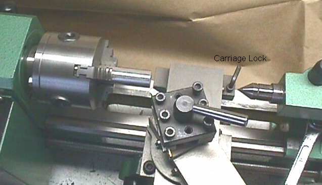
CARRIAGE LOCK.... I made a carriage lock that holds the carriage is a fixed position when you are making a facing cut. I drilled and tapped a ¼-20 hole on the far side of the saddle and inserted the base of a small 17 caliber copper jacketed bullet and then screwed in a ¼-20 socket head cap screw. Tightening the cap screw is an effective carriage lock that clamps the carriage in position when I don't want it to move during a facing operation. The copper bullet protects the ways from damage. A small cylinder of brass or copper would work just as well.
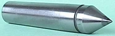
FIXED TAILSTOCK CENTER.... I also purchased a carbide tipped MT-2 tailstock center. It is shorter than a live center and is more accurate. since is does not rotate. I had to shorten it by removing the tang.
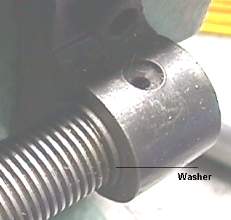
LEAD SCREW PLAY.... There was about 0.025" of axial end play slop in the lead screw. I cut a washer the correct diameter and thickness to remove the lead screw's axial end play and placed it on the lead screw next to the pillow block. See the washer in the photo. Other options are to slot the screw holes and move the pillow block to the left or to put the washer on the left end of the lead screw.
ENGAGING THE LEAD SCREW GEARS.... Most of the time I disengage the gear train while I am machining parts. The gears are noisy and are not really necessary for many cuts. I merely hand feed the hand wheel and it is easy to do. I only engage the gears when I cut threads or really need the longitudinal feed. When I want a ultra-fine finishing cut, I use my Ultra-Fine Power Feed.
CENTERING THE HALF NUTS.... I noticed that the half-nuts when closed were not centered on the lead screw. When I closed them, they tended to lift the center of the lead screw about 0.05". To fix this, I took off the pillow block at the right end and filed vertical slots for the screw holes. With the pillow block screws loose, I then ran the carriage to the right end of the ways and clamped the half nuts on the lead screw next to the pillow block. When I then tightened the screws in the pillow block, the end of the lead screw was lined up vertically with the closed half nuts. I also loosened the two apron bolts and tightened them with the half nut closed on the lead screw to get the correct horizontal alignment on the half nut. Now when I close the half nuts, the lead screw is centered in the half nuts and the lead screw does not shift position.
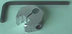
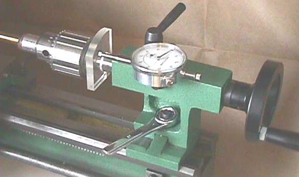
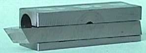
CALIBRATIONS FOR THE TAILSTOCK.... I used my dial indicator and sawed visible marks every 1/8" along the top of the tailstock cylinder so I can read the depth while drilling to at least to the nearest 1/8". I couldnt read the tiny faint metric marks on the side of the cylinder. I also drilled and tapped a hole on the tailstock so I could mount the dial indicator as shown. The Plexiglas piece clamps on the tailstock spindle and the tailstock depth can be read with the accuracy of the dial indicator while drilling holes and trimming rifle cases. Also notice that I took a cheap 17 mm box end wrench and cut off the open end. The box end is just right for the tailstock nut. It stays on the nut and I don't have to hunt for the stock open end wrench when I want to move the tailstock. When you take the tailstock off the lathe and then put it back on, you will notice that the tailstock bottom plate is not square. There is only one position where it will fit correctly. I marked the edge of the bottom plate that faces the chuck with a red Sharpie pen. Now I don't have to try each position and merely rotate the plate until the red edge faces the chuck and it fits.
STIFFEN TOOLPOST AND MORE.... I cut a
2" piece of 5/8" square key stock and clamped it into the side of the
tool post opposite the side used to hold tool bits. This prevents the toolpost
from canting over and makes for better stiffness and better chatter free
cutting. Tool post stiffenss is very important and I dont need 4 tools at
once anyway ;-) My toolpost holds a 3/8" square tool bit so that the top is
right on the lathe center. I grind my tool bits so that I remove very little off
the top and that keeps the cutting edge on center without shims. ![]() NOTE:
There is information on the 7
x 10 Mini Lathe Owner's Group that the new lathes are coming out with tool
posts that are the correct height for 5/16" tool bits.
NOTE:
There is information on the 7
x 10 Mini Lathe Owner's Group that the new lathes are coming out with tool
posts that are the correct height for 5/16" tool bits.
BORING BAR HOLDER.... I made a very solid boring bar holder. I took a 2" piece of the 5/8" square key stock and mounted it in the toolpost and aligned it up parallel to the ways and drilled a 3/8" hole through it long ways. The hole is not in the center of the block, but about 25 mils from one edge (makes it flexible for clamping the boring bar). I used the tailstock to force the key stock onto the drill which was chucked in the 3" 3-Jaw lathe chuck. Then I hack sawed a slot through the thick side of the key stock long ways. Now I have a 3/8" boring bar clamp that is exactly on the lathe's center and needs no shimming for height. It works great with the HSS 3/8" shank boring bars from the KBC catalog listed above. The boring bar holder also has a groove for holding a ¼" tool bit right on center with some adjustment. There is a slight angle to the tool. Pushing the tool forward will raise it slightly. Pictured is a HSS ¼" tool bit ground for thread cutting.
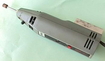
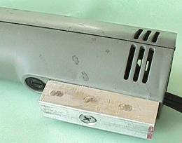
TOOLPOST GRINDER.... I mounted 2"
long piece of the 5/8" square aluminum key stock on the side of my Weller
Mini-Shop Model 601 25000 rpm grinder (about 15 years old) and made it a
toolpost grinder.
MOUNT A 4-JAW CHUCK.... I had an old 4"
Dunlap 4-Jaw chuck and made a back plate for it and mounted it to the spindle
with the same recess and screw pattern that the factory 3-Jaw has. The jaws were
not parallel with the ways, so I ground the inside of
the jaws true with the toolpost grinder. In the Grizzly Industrial catalog, they
have a 4-Jaw chuck for $115. On the message board they talk about a 4-Jaw chuck
that fits the Mini Lathe spindle without modifications that is less expensive.
The J&L Part
Number PCC-19500-A, K72 80MM 3" 4-Jaw flat back chuck will bolt on to the
Mini Lathe. A 4-Jaw chuck is required for turning square or odd shaped items.
TRUING THE 4-JAW CHUCK.... I used the toolpost grinder to true my chuck jaw's clamping surfaces. It makes the jaws parallel to the ways. Here is how I did it. I set the lathe speed to spin the 4-Jaw chuck at about 2000 rpm. The centrifugal force holds the jaws out against the correct surface on each jaw screw. I then used the toolpost grinder to refinish the clamping surface of the chuck jaws parallel to the ways. For each cut, I used a black Sharpie pen to mark the clamping surfaces of the jaws. This way, I was able to tell when the cut cleaned up all four jaws. Each cut was very very light (just barely see sparks or approximately 0.001") and made with about 4 complete pass in and out of the jaw surfaces without increasing the depth of the cut. The 4-Jaw chuck now works very well. Each jaw and slot is numbered so that the jaws are always put in the correct slot. I have indexed the No.1 jaw of both chucks and the lathe spindle with a center punch mark so they are always mounted in the same position. The pictures show the 5/8" key stock bolted and epoxyed to the grinder. The aluminum block clamps in the tool post like a tool bit.
TRUING THE TOS 3-JAW CHUCK.... On a
3-Jaw chuck, grinding the jaws will improve the chucks ability to hold round
work pieces with a minimum of run-out and it will also make the jaw's parallel
to the lathe ways. A while back, KBC had their TOS 4" 3-Jaw chucks on sale
for about $105 and I purchased one. It is a higher quality chuck than the stock
3" 3-Jaw chuck and has 0.875" bore. I made the backplate and it took
me about 6 hours of careful work with lots of careful measurements.
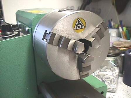
After mounting it, the jaws were out about ± 0.001 checking with a 3" by 3/8" round HSS tool bit, which is very accurately ground. Not too bad! But it could be better, so I got out my trusty toolpost grinder and hit the jaws with a light cut as described above. It was still out about ±0.0005. So I marked the jaws again with a black Sharpie pen and took a extremely light cut. To set the cut depth, I turned the cross slide till I just saw one tiny spark and then backed off about 1 mill and did 4 passes, fore and aft, over the jaws. It barely cleaned up on one jaw and cleaned up the other two. It looked good, so I chucked a 3" by 3/8" HSS Round tool bit and put the dial indicator on it. I turned on the lathe, at low speed, and thought I didn't have contact. I stopped the lathe and advanced the dial indicator. There was NO run-out that I could see on the dial. The needle just stood there! That chuck is right on the money now. I am really pleased with the TOS chuck. Also the heavier chuck will probably make cuts less likely to chatter because of the extra mass. The bore on the 4" 3-Jaw TOS chuck is larger than the spindle bore at about 0.875" ID,. The chuck is TOS Superior Precision made in Czech Republic. It is really high quality compared to the stock chuck and is part #8-802-040 at $145.20 standard price.
TRUING THE STOCK 3-JAW CHUCK.... I have done the same grinding process on the stock 3" 3-Jaw chuck and I got it within ±0.0005. I didn't try the final very fine cut which did the trick with the TOS chuck and will do that one of these days. I actually haven't had the stock chuck back on the lathe since I got the TOS chuck. Be sure and turn the chuck at high speed (~2000 rpm) so that the centrifugal force will hold the jaws against the correct surface of the scroll. Open the jaws until they are opened to a diameter just slightly less than the chuck bore. Here is an easy way to get the correct diameter for the stock chuck. Clamp the jaws on a 5/8" bolt or round stock to seat the jaws, and then remove the round stock and bring the chuck back to the same chuck wrench position is was when it was clamped on the bar stock.
STONE DIAMETER AND DRESSING.... I used a 3/8" diameter stone. Here, a smaller stone, like 3/8" works better than one that almost fits the bore. Don't use a larger diameter stone because it will try to "walk around" from jaw to jaw cutting on the back side. You could mess up your chuck jaws very quickly if this happens. I used the Single-Point Diamond stone dresser (from the KBC catalog above) to true up the stone before I started cutting on the jaws. I just chucked the diamond stone dresser in the jaws sideways to hold it (perpendicular to the lathe axis) in the 3-Jaw chuck like holding a pencil between your thumb and two fingers. NOTE: For this operation if you have a tendency to hit the wrong switch, unplug the lathe. This was just to hold the diamond stone dresser and the lathe motor is OFF and only the grinder motor is on. Then I ran the stone across the diamond point with very light cuts by moving the carriage to dress the stone true.
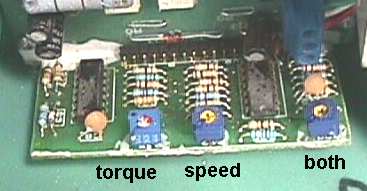
SLOWING DOWN THE SPEED.... I got my lathe down to about 85 rpm. It makes a groaning sound at low speed, but has plenty of torque. There was a lengthy post on the message board by Jose Rodiques on how to change the speed. It is still there, way down on the message board list, if you look for it. Here is how I did it. Mark the original positions on each pot before you make any adjustments. Unplug the lathe and take off the 4 screws over the power panel. Then lay it down and remove the 4 screws holding the plastic cover. Look on the right edge of the small board where there are 3 pots for adjustment. Plug the lathe back in and dial in the slowest speed on the control panel. Use an insulated handle screwdriver in the pots. The "speed" pot slows the lathe speed down and turn it in a direction to slow down the lathe. It will go quite slow, but will start to chatter as it slows too much. Turn the "torque" pot to increase the torque and decrease the chatter. You can hold some resistance on the chuck backplate with your fingers to check the chatter and torque. The top "both" pot seems to help remove the chatter at low speeds too. Too bad some electronic type hasn't put an oscilloscope on the output. I think what this does is generate a good low frequency square wave. Give it a try. If you don't like the results, you can always put the 3 pots back to the original positions.
KNUCKLE BUSTER REMOVED.... I cut off most of the heads of the socket head cap screws on both the cross-feed and compound rest handles to about 0.05" thick and filed two flats so I can use a Crescent wrench to tighten them. I was hitting my knuckles on the long socket head screw. No more banged knuckles. The new camera sure takes clear pictures.
MILLING ATTACHMENT.... I made a milling attachment. I got a 3x3x3 Angle Plate from the KBC Catalog for $9.80 (8-420-102) and a cheap 1-½" drill vise for $11.00 (8-410-060). A better drill vise is the Palmgren 1-1/2" Vise for $38.19 (1-549-5). I removed the compound rest and drilled a similar hole pattern in one face of the angle plate so that it mounts in place of the compound rest and rotates and clamps in any position. On the other face of the angle plate, I drilled two hole patterns so the compound rest could be mounted vertically (either near or far and both with the vise opening at the lathe center line with the compound rest in the center of its travel). Then I removed the toolpost bolt from the compound rest and drilled four 10-32 holes in the top of the compound rest and a similar pattern in the cheap drill vise so I can bolt it to the compound rest. All of this gives me X-Y-Z motion with the drill vise to hold the work and the lathe chuck holds the end mill. I needed to tighten the slide adjustment screws on both the cross slide and compound rest for milling operations, but it works fine. It makes a good end mill for cutter sizes up to ¼" diameter.
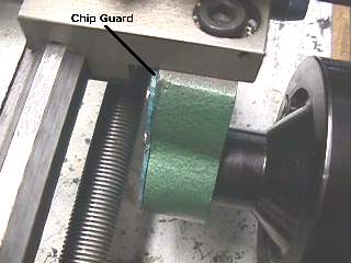
CHIP GUARD.... I made a plastic cover and fastened it to the inside of the apron with 3 tiny 2-56 screws so chips will not get in the hand wheel gears. I was having all kind of trouble with chips getting in there. Now the gears stay clean and run free. You can just see the edge of the piece of green plastic about 1/16" thick on the inside surface of the apron in the above milling attachment picture. Look at about 11:00 o'clock on the hand wheel. Here is a better view of it.
HEADSTOCK PLUG.... When boring a hole, chips wander into the headstock bore and fall into the change gears. I made a plug out of plastic to fit the hole in the back side of the headstock. The plug is a friction fit into the headstock and prevents chips from getting it the gears. When you need something to pass completely through the headstock, it is a simple matter to remove the plug and blow the chips out toward the chuck.
CUTTING MORE THREADS.... The Mini Lathe lists gear settings for 18 different inch threads. Here is a photograph of the gear change chart.
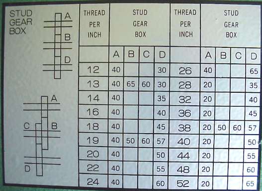
Using only the supplied gears, the Mini Lathe will cut many more inch threads than listed on the chart. Also with only the supplied gears, there are many metric threads that can be cut with sufficient pitch accuracy for a few diameters of thread engagement. I have written a small BASIC program that calculates the gear arrangements for these extra threads. For example, the lathe will cut 8, 10, 11, 56, 64, 72, 80 TPI plus many more threads per inch. The program for calculating the gear settings is free and you can also check the program for correctness by selecting a thread pitch that is already on the lathe's thread chart. Here is an example output for cutting 1 mm threads, 11, and 56 threads per inch.
 A   B   C   D   TPI       MM   % Error
20  35  55  50  25.455   0.9979  0.2143
30  50  60  57  25.333   1.0026  0.2632
30  57  60  50  25.333   1.0026  0.2632
40  50  45  57  25.333   1.0026  0.2632
45  55  50  65  25.422   0.9991  0.0874
50  55  45  65  25.422   0.9991  0.0874

 A   B   C   D   TPI
80  ANY --  55  11.000

 A   B   C   D   TPI
20  35  30  60  56.000
20  35  40  80  56.000
30  35  20  60  56.000
40  35  20  80  56.000
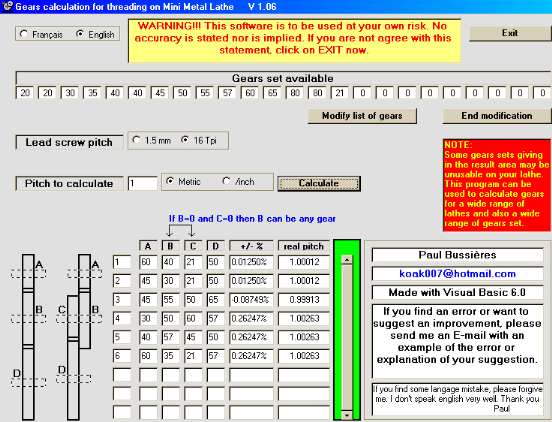
![]() PAUL'S VERSION OF GEARS.... Paul
Bussieres from Quebec, Canada has written a Gears program in Visual BASIC
6.0 that works very well and is quite small. It allows for extra gears and
includes either the inch or metric lead screw. Download the Gears.zip
(28K) file into a junk folder on your C: drive. Unzip it and it will create a
C:\Gears folder. Do a Find for Gears.exe and create a shortcut on your desktop.
Double click on the Gears Icon and run the program. It is easy to understand and
run. It will save your available gears and lead screw type settings on exit.
Note that Paul does not do any checking on gear sizes and some combinations that
are listed might not fit on the lathe.
PAUL'S VERSION OF GEARS.... Paul
Bussieres from Quebec, Canada has written a Gears program in Visual BASIC
6.0 that works very well and is quite small. It allows for extra gears and
includes either the inch or metric lead screw. Download the Gears.zip
(28K) file into a junk folder on your C: drive. Unzip it and it will create a
C:\Gears folder. Do a Find for Gears.exe and create a shortcut on your desktop.
Double click on the Gears Icon and run the program. It is easy to understand and
run. It will save your available gears and lead screw type settings on exit.
Note that Paul does not do any checking on gear sizes and some combinations that
are listed might not fit on the lathe.
![]() The CGTK
Page has easy to use Change Gears page that doesn't require any software.
Look at the INDEX and click on the Change Gears.
The CGTK
Page has easy to use Change Gears page that doesn't require any software.
Look at the INDEX and click on the Change Gears.
This is a reduced size screen view of the GearsVB program. It works
very well and is very easy to use.
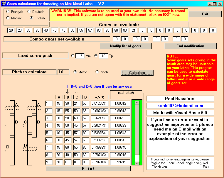
Screen Shot of the Latest Version of gearsvb61.exe
![]() LATEST VERSION OF
GEARSVB.... Paul Bussieres had updated the gearsvb61.exe program. It now is
in English, German, French, & Magyar languages. It also allows the user to
define his gear list and lead screw pitch. Click on gearsvb61.zip
(29Kb) to download the program. Download it to the C:\ folder on your hard drive
and unzip it there. It will create a C:\GEARSVB6 folder and put two files in the
folder. You can go to the that folder and double click on GEARSVB6.exe to run
the program or send a shortcut to your desktop. Let the chips fly. You can
delete the .zip file after the code has been extracted.
LATEST VERSION OF
GEARSVB.... Paul Bussieres had updated the gearsvb61.exe program. It now is
in English, German, French, & Magyar languages. It also allows the user to
define his gear list and lead screw pitch. Click on gearsvb61.zip
(29Kb) to download the program. Download it to the C:\ folder on your hard drive
and unzip it there. It will create a C:\GEARSVB6 folder and put two files in the
folder. You can go to the that folder and double click on GEARSVB6.exe to run
the program or send a shortcut to your desktop. Let the chips fly. You can
delete the .zip file after the code has been extracted.
OLD FILE HAS NEW FEATURE.... If you want to run the gears program in DOS, this if for you. I have updated the BASIC program so that the user can select inch or metric lead screw and can add an additional gear of from (10T to 150T) to the gear set. The small amount of error for the 1 mm metric thread will not affect thread engagements where the nut or female threads are only one or two diameters in depth. To get the program, click on GEARS.EXE (38K) and save the file to a directory of your choice. Open a DOS box and go to the directory where you saved the file and execute GEARS. The program will ask you if you want inch threads or metric threads. Merely follow the instructions. A small file, named TOUT.TXT, will be created by the calculation and it will contain the results displayed on the screen for later printing. Download the GEARS.BAS for the BASIC source. Let me know by email how it runs or if you have improvements. If you are not familiar with DOS, you can also run the program from Windows by going to the folder that contains GEARS.EXE and double clicking on the file. Below is an example run with the GEARS.EXE program selecting a Metric lead screw, an additional 47T gear, and selecting a 1mm thread (the user input is in BOLD RED). For this example, the 47T gear was not needed for the results but was used in the calculations.
This program calculates the gear positions for cutting threads on the
Mini Lathe. For each desired thread pitch it calculates all of the
possible combinations and displays those that work within a reasonable
error. Written by Al Harral on Bethel Island, CA
I have added the additional 21T gear to the standard gear set. If you
don't have the 21T gear, please ignore those setting which include it.
http://www.varmintal.com/alath.htm
Last updated 11/23/1 to add Metric 1.5mm lead screw and an additional gear
Do you have an (I)nch or (M)etric lead screw?? m
The current 15 gears are:
1 20 Tooth
2 20 Tooth
3 30 Tooth
4 35 Tooth
5 40 Tooth
6 40 Tooth
7 45 Tooth
8 50 Tooth
9 55 Tooth
10 57 Tooth
11 60 Tooth
12 65 Tooth
13 80 Tooth
14 80 Tooth
15 21 Tooth
Enter the number of teeth for an additional gear or (0) for none? 47
Do you want an (I)nch or (M)etric thread or (E)nd calculation? m
Metric thread pitch desired mm? 1
A B C D TPI MM % Error
20 ANY -- 30 25.400 1.0000 0.0000
30 ANY -- 45 25.400 1.0000 0.0000
40 ANY -- 60 25.400 1.0000 0.0000
Do you want an (I)nch or (M)etric thread or (E)nd calculation? m
Metric thread pitch desired mm? 1.5
A B C D TPI MM % Error
20 ANY -- 20 16.933 1.5000 0.0000
40 ANY -- 40 16.933 1.5000 0.0000
80 ANY -- 80 16.933 1.5000 0.0000
80 ANY -- 80 16.933 1.5000 0.0000
Do you want an (I)nch or (M)etric thread or (E)nd calculation? E
|
FINE FEED GEAR SETTINGS.... I checked in the Mini Lathe manual, and I do not find the gear settings listed for the 256 TPI feed setting. That is the finest feed possible with the stock gears and here are the settings. This is still a pretty coarse feed for finishing cuts.
A B C
D TPI
20 80 20 80 256.0 Fine Feed
METRIC GEARS.... Mike Carrollton made these gear
measurements on the Mini Lathe's change gears:
module = 1.0
pressure angle = 20°
bore = 12 mm
face width = 8 mm
keyway width = 3 mm
keyway height (above bore) = 1.4 mm minimum
METRIC GEARS CHEAP.... All Electronics Corp has various metric gears with the same pitch at the change gears as on the Mini Lathe. If you do a search and look for gears, you will find them. They have a 5 gear set that is 10T, 20T, 30T, 40T, and 50T that is very reasonably priced. The holes are a different size, but with a Mini Lathe extra jack shafts can be made to fit them.
ADDITIONAL GEAR.... Chadd Thompson, from the 7 x 10 Mini Lathe Owner's Group, found a source for 21T gears that will fit the Mini Lathe with some modification. It took me about an hour to open up the bore, cut the gear to the correct width, and file a keyway in it. The additional gear is for cutting Metric threads more accurately than with the stock gears. The best of all worlds, would be a 127T gear, but the diameter would be 5-1/8" and it wouldn't fit on the lathe. The next best gear would be one of approximately half that size or 63 teeth. But a smaller gear would be almost as good except for the 3 mm thread. I have run the GEARS code with an additional 21T gear for the following Metric thread pitches. You can get an idea of the improved accuracy for Metric threads for adding an extra gear of 18, 21, or 63 teeth. The 18 tooth gear has an additional advantage in that it would be useful for the fine feed where it would allow a feed of 284 TPI, compared to the standard 256 TPI with the stock gears. In the Table, the bold numbers show an improvement over stock gears. I have ordered the Boston Gear catalog for spur gears. They are supposed to have gears in "open stock". Also, if they are not too expensive, a couple of 96 tooth gears would make a 368 TPI fine feed for finishing cuts.
WITH A 21 TOOTH GEAR....Here is a table of gear settings for Metric threads with the stock gears plus an extra 21T gear included. There are more combinations that work, but I have made sure that a large gear is on the lead screw to improve the mechanical advantage in turning it. I had to change the BASIC program to include the extra gear. The GEARS.EXE program now includes the 21T gear.
| Metric Thread (mm) |
A | B | C | D | %Error |
| 0.5 | 60 | 50 | 21 | 80 | 0.0125 |
| 0.75 | 35 | 57 | 50 | 65 | 0.0225 |
| 1.0 | 60 | 40 | 21 | 50 | 0.0125 |
| 1.25 | 60 | 20 | 21 | 80 | 0.0125 |
| 1.5 | 40 | 50 | 65 | 55 | 0.0606 |
| 1.75 | 40 | 35 | 55 | 57 | 0.0358 |
| 2.0 | 40 | 35 | 55 | 50 | 0.2143 |
| 3.0 | 65 | 50 | 80 | 55 | 0.0606 |
NOTE: I have been getting feedback that people are having problems running the GEARS.EXE program. The program runs on a PC. I don't know if it will run on a Mac with PC simulation software. The Netscape browser, it seems to change the GEARS.EXE program, during downloading, so that it won't run. If you have a problem, email me and I will attach the file to a return email. If you would like a copy of GEARS.BAS, the BASIC source, which runs with QBASIC, I will send it to you.
CASE TRIMMER.... I have mounted the dial indicator on the tailstock so that I can trim the length of cartridge brass and read the length on the dial indicator as I cut. This setup makes a first class case trimmer. The High Speed counter-bore cuts much better than the carbon steel cutter on my old RCBS case trimmer. I do a number of reloading operations on the Mini Lathe. It is a very handy tool on the reloading bench.
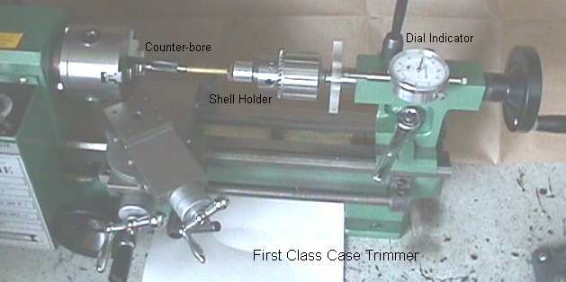
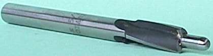
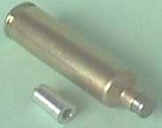
Here is the High Speed counter-bore with a tight fitting pilot (made from the valve stem of an old engine intake valve - really tough steel) that fits the case mouth and the shell holder that fits in the tailstock chuck. The pilot was finished with 600 grit paper and then polished with Flitz Metal Polish on a rag. This gives a very smooth finish so the pilots turns smoothly in the case mouth. The HSS counter bore is a 7/16" 3-fluted counter bore with a 5/32" pilot hole and a 3/8" shank that I got from KCB Tools.
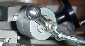
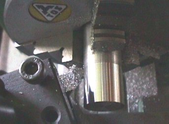
QUICK CHANGE TOOLPOST.... I have the QC Toolpost from TS Engineering. It is sturdy, the correct size for the 7x10 lathe, and very well made. It is easily adjustable for the correct tool height. Here is a photo of it in operation taking a finishing cut on a cylinder of aluminum. The toolpost also has two tool holders for 3/8 inch or smaller tool bits and a tool holder for a 3/8" shank diameter boring bar.
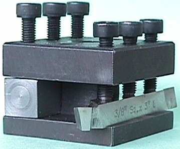
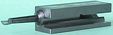
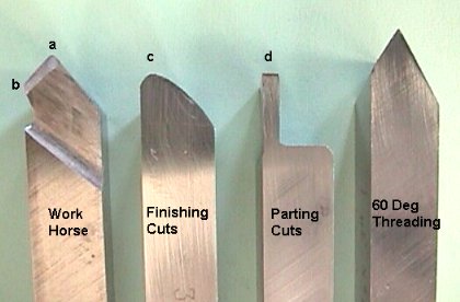
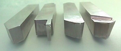
TOOL BIT GRINDING.... Tool bit grinding is an art form in itself. It is fun to look through a machinists tool bit collection for the way his tool bits are ground. With a little practice, you will find other useful tool shapes that work, but this is a good start for the beginner. Here are the four 3/8" square HSS Tool Bits I use most often for general purpose on mild steel, aluminum, and brass. The Work Horse tool gets the most use. It is primarily made for removing metal fast and easily. The point (a) is where most of the cutting is done toward the chuck. The included angle at (a) is about 80° so the tool can be rotated to cut to a 90° shoulder. The edge between (a) and (b) is parallel to the top surface of the tool top face and is the cutting edge. The point (b) is used for facing cuts as the tool travels toward the center using the cross slide. The second view shows the points of the tools so you can see the angles of relief and rake. The tool for Finishing Cuts has a rounded cutting surface (c) and is only useful for fine cuts. The Parting tool makes about as wide and deep a parting cut you can make with the Mini Lathe. The width at (d) is about 0.080" wide and will cut about 0.3" deep. You merely plunge the tool where you want to cut-off a piece of work. If you need a deeper cut than it will accomplish, you finish it off with a hack saw. The 60° Threading tool works for both Inch and Metric threads. All of these tools are ground to work with the cutting edge at the lathe center and the shank mounted parallel to the cross-slide travel. On my lathe, the top surface of a 3/8" tool bit is right on center when clamped in the 4-Way tool post. There is an end view of the same four Tool Bits so you can get an idea of how they are ground.
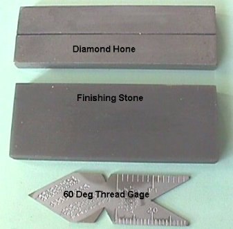
SHARPENING THE CUTTING EDGE.... After grinding the tool points, the cutting edge will need honing. The Diamond Hone works very well to sharpen the cutting edge of both HSS and carbide Tool Bits. The Finishing Stone is very fine and puts a very good edge on the HSS Tool Bits. If you are going to cut threads, you will need a 60° Thread Gauge as a template to grind your tools and when you setup the tool for cutting. To position the tool, hold the gauge on the tool point and make sure the opposite side is parallel to the work or lathe axis.
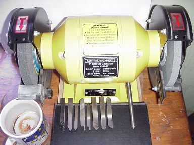
TWO WHEEL 6" GRINDER.... To grind Tungsten Carbide tool bits, you
will need a Green Silicon Carbide grinding wheel. They are actually
"softer" (wear away faster) than the Grey Aluminum Oxide grinding
wheels used for HSS tool bits. I have a 80 g 6"x3/4" wide medium grit
Grey Aluminum Oxide wheel on the left side and a 6"x1/2" wide fine 120
grit Green Silicon Carbide wheel on the right side of my grinder. I grind my HSS
tool bits on the medium grit wheel. I have a cup of cold water for keeping the
tool bits cool. After I finish grinding the desired shape, I make a final
smoothing cut on the Silicon Carbide wheel which leaves a very fine finish. Then
I hone the tool bit to get it really sharp.
The Aluminum Oxide wheel will not readily grind the carbide tool bits and merely
heats them up and dulls the grinding wheel in the process. The Silicon Carbide
wheel grinds the Tungsten Carbide tool bits well, but the wheel wears away much
faster than an Aluminum Oxide wheel.
KEEP IT COOL.... After grinding for 10 to 15 seconds plunge the tool bit
in the cold water to keep it cool. It becomes like art to continue grinding at
the same place and angle between trips to the cup of cold water.
GET A DIAMOND.... I would suggest getting a single point diamond wheel
dresser. The one I have is a 1/3 carat diamond on a 3/8" shaft and only
costs about $5.20 from KBC. Also after you mount the grinding wheel, and tighten
the nut, rotate it by hand and see if the face runs true. If it doesn't, fuss
with it a bit and try different positions until the run-out is the best you can
get. This simple step helped quite a bit in reducing grinder vibrations. Then
true the face with the diamond wheel dresser. Do your grinding on the face of
the wheels, not on the sides.
ENGAGING THE LEAD SCREW GEARS.... Most of the time I disengage the gear train while I am machining parts. The gears are noisy and are not really necessary for many cuts. I merely hand feed the hand wheel and it is easy to do. I only engage the gears them when I cut threads or really need the longitudinal feed. When I want a fine finishing cut, I use my Ultra-Fine Power Feed.
MAKING A SMOOTH FINISH CUT.... Getting a smooth finishing cut with brass or aluminum is relative easily done with a very sharp round nosed finishing HSS tool bit and a fine lead screw feed. If you try the same thing with mild steel, it will look and feel rough in comparison. Here is something to try and see how it works. On a piece of mild steel stock about ½" in diameter (a 1/2" bolt will work fine) running at about 300 rpm, take a finishing cut with the rounded finishing tool where you remove about 0.003" on a diameter with the cut. Check the looks and feel of the cut. It will be rough to the touch and feel like a cat's tongue. Advance the tool another 0.0015" and remove another 0.003" finishing cut, but before you do, rub a light film of Crisco (I use Butter Flavored Crisco) over the surface. Just this tiny amount of lubrication will make a marked difference in the smoothness of the final cut. The lubrication will allow the chip to curl up and away from the cutting area and not get caught between the edge of the tool and the work.
FINE FEED GEAR SETTINGS.... This is the finest feed possible with the stock gears and here are the settings. This is still a pretty coarse feed for finishing cuts.
A B C
D TPI
20 80 20 80 256.0 Fine Feed
ULTRA-FINE POWER FEED.... I have installed a tiny 2.5 rpm motor on the end of the lead screw to provide an ultra-fine power feed for super smooth finishing cuts. I got the motor from Micro-Mark, item #82090 Animation Gearmotor for $14.95. The picture shows the motor mounted on a 1/4" thick plastic plate screwed to the end of the lathe bed. I had to make an extension to the lead screw by drilling and tapping the end to accept a 1/4-20 stud and facing the end square. There is a short aluminum shaft that extends to accept the motor shaft. The motor shaft has an 1/8" diameter cross hole in the 0.275" diameter shaft. I used a piece of bamboo shish kebab stick for a shear pin. Don't laugh, it works! By the way, I use these bamboo shish kebab sticks for a lot of different things. They work fine for mixing epoxy, annealing case necks, and any use that requires a long shaft that is strong and flexible.
This is a BAD IDEA. This 4.8 rpm gear motor does not have enough torque to
move my carriage. Stick with the Micro-Mark motor. It is slow, but makes a very
smooth cut. Here is another source for a cheap gear motor. All
Electronics Corp has a 4.8 rpm geometer, CAT# ACM-104 for $2.50.
The extra speed is probably the way to go. Also while you are there, get their
catalog. It is a "must have" for goodies around the shop. They do have
a number of gears in the catalog that are the same pitch as the change gears on
the Mini Lathe. The 5 gear set, 10, 20, 30, 40, and 50 set mesh very nicely with
the change gears.
I just finished testing the installations and it works great. The tiny motor has enough torque to move the carriage with the forces required for a finishing cut. I made a 1" long cut on a piece of aluminum and it was as smooth as mammary skin! I left the 80 tooth gear on the left end of the lead screw, but removed the "B" gear set altogether. I can hold the 80 tooth gear by hand and it merely stalls the motor, and when I release it the motor starts back up. There is no damage to the motor when that happens. The motor must have plenty of internal impedance to resist heating. I took a 1" long finishing cut in aluminum 6061-T6 and it took about 6 minutes. The finish is very smooth, accurate, and nearly polished. Notice that the chips are tiny flakes and some were so fine they were actually floating in the air. The spindle speed was about 600 rpm and I figure the feed was about 0.00025" per revolution. Here is a picture of the finishing cut and notice the dust fine chips.
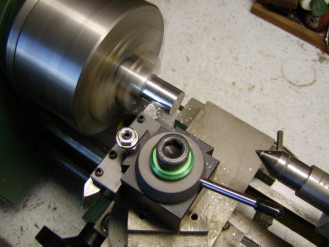
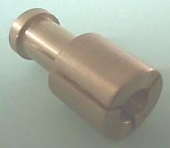
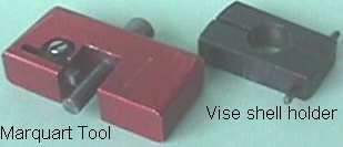
NECK TURNING CARTRIDGE BRASS.... I have made a batch of 22-250 Improved brass with fitted necks and I did the neck turning using the Mini Lathe and my Marquart tool. If cartridge brass is chucked in the 3-Jaw chuck, they are dented so I chucked the cartridge brass in the lathe with a brass collet. With the lathe running at its slowest speed (~185 RPM), I held the Marquart outside neck turning tool by hand. The brass collet chucks in the 3" 3-Jaw chuck and the shoulder sets against the face of the chuck. The three slots in the brass collet give it enough flexibility to clamp the case head without yielding the brass fingers. The vise shell holder, in the picture, is needed if you use a bench vise to hold the brass and turn the tool (the old way) by hand. The dimensions of the brass collet are given. Change the 0.472 diameter to fit the cartridge of interest.
CHAMBER LENGTH GAUGE.... Make your own chamber length gauge for measuring the length of your rifle's chamber. Often the case lengths listed in the reloading manuals are much shorter than your rifle's chamber length. If you trim your cases to this length, there is a large gap that the bullet must jump across as it leaves the case mouth and enters the rifling. Here are the dimensions for making your own chamber length gauges for a few calibers. You can find the dimensions for other calibers in your reloading manual.
Machine the chamber length gauge out of what ever metal that is available, such as a steel or brass bolt, stainless steel bar, or brass. The easiest way to make the chamber length gauge is to let about 3/4" of the bolt or bar stock stick out of the chuck and machine the diameter "B" for about 0.5". This will give you plenty of room to make a measurement with your micrometer. Then turn the tool so it will cut to a 90° shoulder and machine diameter "A" on the end. Cut the chamfer at the end so the chamber length gauge will easily start in the case mouth. Touch up the finish with some fine sand paper. Use the parting tool to cut off the chamber length gauge from the stock. Leave the rim at diameter "B" about 0.030 to 0.040" thick when you cut it off. Then turn it around and chuck on diameter "A" and carefully face off the head at diameter "B" so it is flat. If your tool bit is not right on the center, you can take a center drill and just "start" a hole in the head so that there will not be a high spot at the center. Smooth the end with sand paper being careful to not round the corner on the edge of the flange and it is done.
| Rifle Caliber | Dimension A (in) |
Dimension B (in) |
| 17 Rem | 0.172 | 0.199 |
| 22 Hornet | 0.224 | 0.244 |
| 221 Rem Fireball | 0.224 | 0.250 |
| 222 Rem | 0.224 | 0.253 |
| 223 Rem | 0.224 | 0.253 |
| 22-250 | 0.224 | 0.255 |
| 243 Win | 0.243 | 0.276 |
| 25-06 | 0.257 | 0.290 |
| 7mm Rem Mag | 0.284 | 0.313 |
| 30-06 | 0.308 | 0.340 |
For each caliber, you will need to make a special altered cartridge case to use for making the chamber length measurements.
To use your new chamber length gauge to measure length, start the chamber length gauge in the neck of the specially prepared case and chamber the case in your rifle. Extract the case and measure the over all case length with your dial calipers. Compare the length with what is listed in the reloading manual. I trim my cases so that there is about 0.005 to 0.010" clearance in length. I measure my case lengths after each firing to make sure that they have not closed that gap. If the case mouth does contact the end of the chamber, it will clamp the bullet in the case mouth and excessive and dangerous pressures will result. Often you will find that there is a large gap of 0.050" or so in your chamber and if the recommended trim length is used.
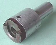
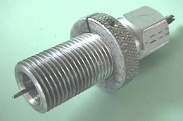
UNIVERSAL DECAPPING DIE....
Here is an aluminum universal decapping die, for removing the primers from
calibers 17 Ackley Hornet to 300 Win Mag, that I made on the Mini Lathe. The
threads are 7/8-14 and I did this job before finding out how to slow the lathe
down. At about 185 RPM, the tool was really advancing fast. I only ran the tool
into the chuck once! Of course I lost the index and had to "pick up"
the thread again to continue. Now with the Mini Lathe's slow speed of about 70
RPM it would be much easier job to cut the threads.
LATHE BIOGRAPHY.... I was about 10 years old when I started working on Pop's 10" Atlas lathe* when he wasn't looking. I had watched everything Pop did on the lathe from the very first day he got it. My first project was a "bean shooter" which was a piece of mild steel about 4" long with a ¼" hole through it and fancy shapes on the outside. Each time I used the lathe, I tried to put everything back just like it was before I started, but Pop found out. He didn't even get mad, but just told me to be careful and gave me some instructions. I was in kid heaven. Then I made a tiny ball peen hammer with a round hole for the handle and found out why the holes in a hammer head are elliptical. The hammer head would twist on the handle when I tried to use it. I spent hours grinding a knife blade out of a piece of hot rolled bar stock. I had it all finished and showed it to Pop and he said it was no good. Pop was right, I couldn't sharpen it. That is when I learned there is a difference between iron and steel.
*Click on the Atlas
10" Lathe to see a full sized picture. The original 1936 model with
integral "Overhead" countershaft drive. No power cross feed was fitted
to these early machines. This picture brings back old memories.
MACHINING FOR PAY.... When I was about 12 or 13, Pop was
converting bolted crane boom sections to quick disconnect crane sections. Each
junction had four 2" pins, one on each corner. The male pin sockets needed
to be 2-3/8" thick. All Pop could get was 2-1/2" stock and he paid me
50¢ a piece to face off the sockets to the correct thickness and bore the flame
cut hole to the correct diameter for the pins. I was kid rich! A couple years
later, Pop bought a 16/24" x 12' South Bend lathe (a 16" lathe blocked
up to 24") for the welding shop. He still has that old lathe. When I took
machine shop in high school, instead of making the standard projects, the
teacher let me make tooling for the home South Bend lathe. I made a vertical
toolpost block to use instead of the offset toolpost block which was offset for
turning up to a 24" diameter but a pain for anything under 6" or so. I
also made a multi sized boring bar holder for bars up to 2" in diameter. I
made the boring bars and hand filed square holes in each end. I also made some
large live cone centers and a bunch of other tooling.
NEEDED A TRACTOR.... We had 5 acres and Pop needed a tractor,
so we made one. It had a '39 Plymouth 6 cylinder L-head engine, a Dodge truck
transmission, a Studebaker front axle, 6" heavy wall pipe frame and the
rear end was out of a White truck. Pop got two tires about 5 feet in diameter
from a motor grader for the rear wheels (one had a bald spot where part of the
tread was ripped off). Well, when it was all put together, we fired it up and it
would go about 15 MPH in first and 40 MPH is second gear (making the whole
tractor bounce from the flat spot on one tire) and you couldn't begin to get it
into third or forth gear. Not to be discouraged, Pop got some big gears and we
built a gear reduction box between the transmission and the rear end. I did the
machine work on the hubs that were welded into the box to hold the ball bearings
and seals. When it came time to put a cover on the gear box, Pop just welded the
cover on. It had half inch thick end plates, a fill plug in the top and a drain
hole in the bottom and welded on cover and it was strong. It didn't leak and you
could hoist the tractor in the air by the transmission if you wanted. It was
positioned just right for the foot rest while driving the tractor.
With the new gear box, the tractor would go so slow in first gear that you had
to almost reach out and feel the top of the wheels to see if it was moving. But
it was just right for plowing in 3rd gear with plenty of pulling power. When we
built the gear box, we meshed the gears a tad to close, center-to-center and it
made a lot of noise and after about 15 minutes of plowing, it got so hot, you
couldn't put your feet on it. That is when I learned about molybdenum disulfide
as a lubricant. Pop got some used Moly transmission oil and put it in the gear
box and what a change. The noise was greatly reduced and the gear box would just
keep your feet comfortably warm.
SUMMER JOB AT BAKERSFIELD MACHINE.... In the summer after my
junior year in high school, I got a job at Bakersfield Machine. The man that
sold the welding supplies (part of the Bakersfield Machine at the time) knew me
and got me the job for $0.75/hr. I told them that I wanted to run one of the
lathes and they gave me a broom and told me to sweep up the shop. Well, I did
and in 4 hours you can do a lot of sweeping. I guess I was sort of bugging one
of the machinists and was by his lathe waiting for new chips to sweep. The
foreman got a call and he had to go offsite and bore out a Caterpillar engine
cylinder. He was using the portable boring mill to bore out track rollers for a
D-8 Cat. They wear down in diameter and the welder would build them up on the OD
by welding. The weld shrinkage would decrease the bore, so the bearings would no
longer fit inside. The ID needed to be bored out about 0.020" so the
bearings would fit. Well, the foreman called me over and told me to use the #3
lathe and chuck the roller in the 3-Jaw chuck and bore out one end to the right
size, them turn it around and bore out the other end. He set his inside
micrometer to the correct size and took off for the field job. The job was to
chuck one end of the roller in the external jaws of the 12" 3-Jaw chuck and
tap the high side of the other end until it turned true and then bore it out to
the correct size. Then swap ends and repeat. Actually, it was really an easy
job. When the foreman got back, I had finished all of the rollers and was back
sweeping the floor. He kind of got mad and said, "I told you to bore those
Cat rollers!" I told him that they were all finished. He went over and set
his inside micrometer and started checking the bores for size. He did about 4 or
5 of them and then looked up and smiled and told me to put up the broom, the #3
lathe was mine and they would hire a floor sweeper! The next week, I got a raise
to $1.65/hr and again it was kid heaven. I had an old 39 Plymouth, gas was 19
cents a gallon, a girlfriend that liked to go fishing and I was living high on
the hog. I got the same job the next summer too, but a new girlfriend.
USE THE #3 LATHE.... The #3 lathe was ancient, like all the
lathes in the shop. It was 24"x20 ft bed with a big overhead flat belt
drive and was so badly warn that you couldn't cut threads at the chuck. To cut
threads on a pump rod, you had to use a steady rest and move out about 4' from
the chuck where the lead screw was not so badly worn.
100 TON PRESS.... About this time, Pop wanted to build a 100
ton hydraulic press. I did all the machine work making the 6" ID cylinder
(composed of a 6" pump liner surrounded by an 8" pump liner with a
poured in place lead liner). The ram was a 4" diameter shaft, and nut with
double pitch square threads. I also made a two cylinder hydraulic pump out of a
piece of 3" square truck front axle and the crankshaft for the 2 cylinder
pump. The press is still in use today, but the pump was too slow and has been
replaced with a much faster positive displacement hydraulic pump. Pop said that
when high forces are required they have to resort to the old two cylinder pump
to get the required pressure.
 Here is Pop making a
cut on the old 16/24" by 12' bed South Bend lathe. It is hard to see but he
is using the vertical toolpost extension I made in High School. He is a good man
from the days when a hand shake was a contract and he never lied to anyone.
Cheating is not in his vocabulary. I have written a Tribute
to Pop on Father's Day, June 20, 2004.
Here is Pop making a
cut on the old 16/24" by 12' bed South Bend lathe. It is hard to see but he
is using the vertical toolpost extension I made in High School. He is a good man
from the days when a hand shake was a contract and he never lied to anyone.
Cheating is not in his vocabulary. I have written a Tribute
to Pop on Father's Day, June 20, 2004.
COLLEGE & THE DRAFT.... One year at Berkeley and I flunked
German. Pop wouldn't pay for anymore of that quality of study, so back to
Bakersfield. One year at Bakersfield J.C. and then I got drafted for 2 years in
the Army and off to Korea playing bassoon in the band. That's another story, but
later...
LIQUID HYDROGEN.... When I got out of the Army, I got a job in
Bakersfield at Hopper's Machine selling nuts, bolts and parts, but refused to
join the machinist union and got fired after 2 months. I had been delivering
parts to this super secret Stearns-Rogers plant with guards and a high fence out
in the oilfields. The day after I got fired, I applied for a job at
Stearns-Rogers and got a job as an operator making liquid hydrogen rocket fuel.
It was so secret at the time, we couldn't say the word hydrogen and had to talk
about "liquid product". It was quite an operation starting with the
waste products, hydrogen, methane and other hydrocarbons from the Mohawk
Refinery Cracking Plant in Bakersfield. It was my first taste of cryogenics. In
the first hour we went into production, we produced more liquid hydrogen than
had ever been made in the world up to that time. Well, I told them about my
machine shop experience and they had me drive to LA and pick out a used
government lathe from what must have been a 2 acre warehouse full of machinery.
Since money was no object, I picked out about a sturdy 16x72 geared head lathe
that had all the tools. I still worked as a process operator but occasionally
would do machine work for them.
 MECHANICAL
TECHNICIAN.... After 2 years of making liquid hydrogen on shift work,
with various fires, and
MECHANICAL
TECHNICIAN.... After 2 years of making liquid hydrogen on shift work,
with various fires, and explosions I developed an ulcer. So I applied at the Lawrence Livermore
Radiation Lab (name at that time) and got a job as a mechanical technician. Back
to the lathes and machine shop. I was using quality machinery building all kind
of special scientific parts and turning exotic materials. I got to make a trip
to Christmas Island when Russia broke the treaty and started atmospheric nuclear
testing. The Lab fired off a number of atmospheric nuclear tests off Christmas
Island and my job was to load film into a very high speed camera. It was called Operation
Dominic Fireballs, Pacific Testing 1962, near Christmas Island Area -
1962 I remember the magnitude of the first nuclear event I
witnessed, it must have been YESO. We used arc welding dark glass over our eyes
and the device was dropped from an aircraft and detonated at something like 10K
ft at a horizontal distance of 5 miles. Well the device's yield was more than
expected. The intense bright light was burning my face. It felt just like my
face was 6 inches over a gas flame and it was on fire. I was just about ready to
get out of the light and it started to decrease. About 30 seconds and the blast
wave went through. We were suppose to hold our mouth open and plug our ears with
our fingers so we wouldn't burst an eardrum. Remember, this was 1961 and in the
old days where there was no EPA and people were not afraid of their shadows. The
trailer's rear end was pointed toward the blast. The blast wave caved in the
back end of the 18 wheeler trailer about 1 foot. The front of the Quonset hut
mess hall was blown in about 6 feet. After that, they moved all detonations off
to 15 miles! Everyone felt better about that.
explosions I developed an ulcer. So I applied at the Lawrence Livermore
Radiation Lab (name at that time) and got a job as a mechanical technician. Back
to the lathes and machine shop. I was using quality machinery building all kind
of special scientific parts and turning exotic materials. I got to make a trip
to Christmas Island when Russia broke the treaty and started atmospheric nuclear
testing. The Lab fired off a number of atmospheric nuclear tests off Christmas
Island and my job was to load film into a very high speed camera. It was called Operation
Dominic Fireballs, Pacific Testing 1962, near Christmas Island Area -
1962 I remember the magnitude of the first nuclear event I
witnessed, it must have been YESO. We used arc welding dark glass over our eyes
and the device was dropped from an aircraft and detonated at something like 10K
ft at a horizontal distance of 5 miles. Well the device's yield was more than
expected. The intense bright light was burning my face. It felt just like my
face was 6 inches over a gas flame and it was on fire. I was just about ready to
get out of the light and it started to decrease. About 30 seconds and the blast
wave went through. We were suppose to hold our mouth open and plug our ears with
our fingers so we wouldn't burst an eardrum. Remember, this was 1961 and in the
old days where there was no EPA and people were not afraid of their shadows. The
trailer's rear end was pointed toward the blast. The blast wave caved in the
back end of the 18 wheeler trailer about 1 foot. The front of the Quonset hut
mess hall was blown in about 6 feet. After that, they moved all detonations off
to 15 miles! Everyone felt better about that.
In-between atmospheric test detonations, when all the preparations were done,
we had free time. I would take one of the jeeps and drive the surf looking
for aluha (amberjack). Here is a photo of one that went about 40 pounds. The
cooks liked to eat these raw. They did like them a little smaller than this. We
ran out of fishing line and were using braded nylon electronic cable tie cord
for fishing line and making our own lures in the machine shop trailer.
BACK TO SCHOOL.... When I got back to the states, I was
transferred over to provide mechanical technician support for Cryogenics. We
built the first superconducting magnet in the shape of the seam on a baseball.
The 3D curve is the intersection of a sphere and a hyperbolic-paraboloid. I
started learning Fortran programming by going through the trash cans and finding
discarded printouts. See the Computer Page for info on
the one million dollar IBM 1401 computer that I was using. Later I got a
McCracken's Fortran II manual and wrote a code to mill the baseball seam track
on a sphere so we could make the magnet. This was well before CNC machines.
During this time, I took a class in differential equations and aced it. So I
decided to go back to college and get an engineering degree. See the Engineering
Page. After I received my BS in General Engineering, it ended my work
with lathes and machinery. I worked a total of 30 years at Lawrence Livermore
National Lab and retired in 1990. After about 8 years of retirement and
Engineering Consulting work, I got my Mini Lathe. I checked a lot of catalogs
and had a lot of lathes circles, but none of them would fit in my tiny
computer/reloading room. I finally settled on the Harbor Freight Mini Lathe and
haven't regretted it. It is nice to have a lathe and a mini machine shop again,
even though it is very small scale. Now, when something breaks or I need a new
part, I think lathe instead of heading for the hardware store.

WAC.... Here is my favorite single frame from Dilbert.
Mary Ann pasted this on the bathroom mirror for me years ago.
I am WAC positive.
| Tap Size | Thd Per Inch | Tap Drill | Clearance Drill |
| 0 | 80 | 3/64 | 52 |
| 1 | 64 | 53 | 48 |
| 1 | 72 | 53 | 48 |
| 2 | 56 | 50 | 43 |
| 2 | 64 | 50 | 43 |
| 3 | 48 | 47 | 37 |
| 3 | 56 | 45 | 37 |
| 4 | 36 | 44 | 32 |
| 4 | 40 | 43 | 32 |
| 4 | 48 | 42 | 32 |
| 5 | 40 | 38 | 30 |
| 5 | 44 | 37 | 30 |
| 6 | 32 | 36 | 27 |
| 6 | 40 | 33 | 27 |
| 8 | 32 | 29 | 18 |
| 8 | 36 | 29 | 18 |
| 10 | 24 | 25 | 9 |
| 10 | 32 | 21 | 9 |
| 12 | 24 | 16 | 2 |
| 12 | 28 | 14 | 2 |
| 14 | 20 | 10 | D |
| 14 | 24 | 7 | D |
| 1/4 | 20 | 7 | F |
| 1/4 | 28 | 3 | F |
| 5/16 | 18 | F | P |
| 5/16 | 24 | I | P |
| 3/8 | 16 | 5/16 | W |
| 3/8 | 24 | Q | W |
| 7/16 | 14 | U | 29/64 |
| 7/16 | 20 | 25/64 | 29/64 |
| 1/2 | 13 | 27/64 | 33/64 |
| 1/2 | 20 | 29/64 | 33/64 |
![]()
|
|
||||
|
|

Last Updated: 12/10/2014
End of Page![]()