
This analysis was done with the LS-DYNA Finite Element Code. This code is a very powerful tool for analyzing the dynamic and static loading of structures.
The loading condition is 50,000 psi on the face of the bolt. This it the equivalent force that would be applied to the bolt face from a 223 Rem caliber with a case head separation. The components in the calculation remain in the elastic state. There is no yielding of the 4140 steel, so the stress levels may be linearly scaled as long as the maximum effective stress level remains below the 120,000 psi yield stress. The dimensions of the model were taken from my Stolle Panda rifle in 23/40 caliber. This caliber is essentially a long neck 223 Ackley Improved with the neck to shoulder junction set back about 0.1". In the model, the Z-axis is inline with the bullet's path, see the triad in the lower left corner of each view. There is info on how could actually measure a representative chamber pressure here: Recreational Software, Inc. Software & Instrumentation Technology for the Shooting Sports.
A more complete FEA analysis of the Remington Model 7 action including the bolt, action, recoil lug, and barrel.
The material properties for the 4140 steel were implemented with a power law hardening model that allows for plastic flow if the effective stress (Huber-Hencky-von-Mises stress) exceeds the 120 ksi yield stress.
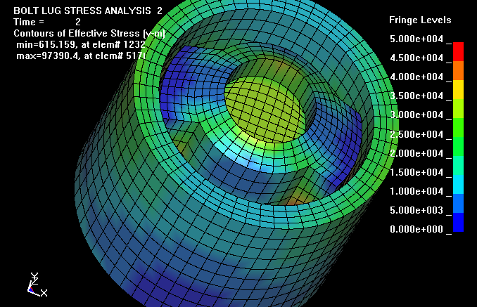
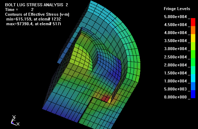
The maximum effective stress level of 97,390 psi is located at the surface of
the bolt lugs where they contact the receiver. For 50,000 psi in an intact 223
Rem case, the maximum effective stress level would be about 63,500 psi and well
below the yield stress. This view of the bolt, lugs, and receiver does not
clearly show the location of the high stresses. In the analysis, the top plane
of the receiver, shown in the view, is fixed in the Z-direction and the pressure
is applied to the bolt face. For simplicity, the firing pin and hole was not
included in the mesh. The contact surface between the bolt lugs and the receiver
was modeled with a sliding surface including a 0.3 friction coefficient.
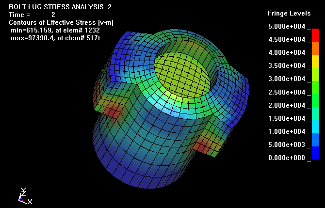
This view of the bolt and lugs, shows more clearly that the high stress levels
are located at the lug contact surfaces.
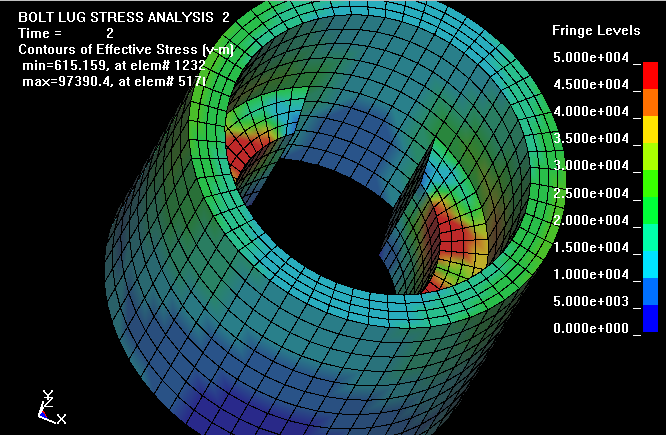
This view of the receiver shelf shows the high contact stress levels where the
bolt lugs rest.
This it the actual mesh used in the calculation. An X-Z plane of symmetry and
Y-Z plane of symmetry were used in the model. Using these two planes of symmetry
requires a much smaller mesh and gives results identical to what a full 3-D mesh
would give.
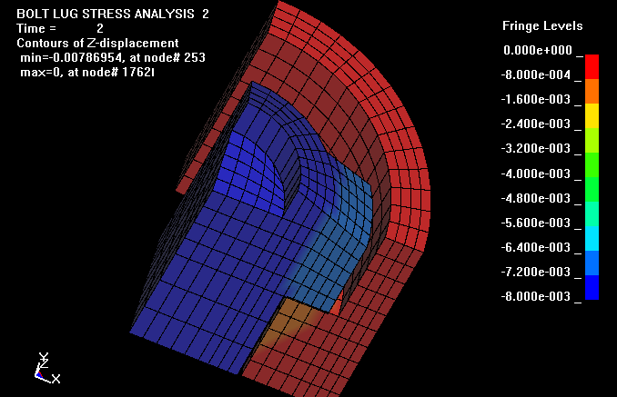
Here are the fringes of axial displacement in the Z direction. The bolt face
moves rearward about 0.0077". There is about 0.0002" of slop in the
model before the contact surfaces from the bolt lugs to the receiver shelf start
to load each other. This was intentional so that when the mesh was being made,
certain nodes wouldn't be removed. This displacement with a 50,000 psi pressure
on the bolt face would be equivalent to a non ruptured 223 Rem brass case with
about 76,600 psi internal pressure. For an intact 223 brass case head with
50,000 psi internal pressure, the bolts rearward deflection would be about
0.005". This amount of bolt deflection is twice that calculated
by Dan Lilja of Lilja Precision Barrels, but his calculation was only for
the bolt lugs and did not include the deflections of the lug contact points and
a slight amount of stretch in the receiver from the barrel threads rearward. The
magnitude of the action's axial deflections is one more reason that the chamber
should be low friction and allow the brass case head to contact the bolt face
early in the firing sequence.
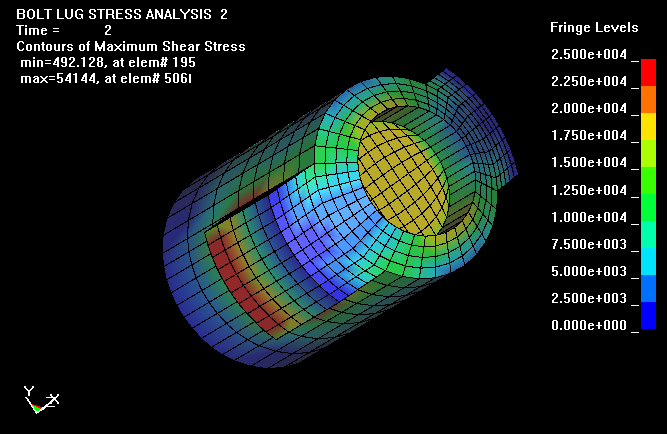
Finally, this plot shows the fringes of maximum shear in the bolt. However, in
this view, one can not view the shear stresses at the junction of the bolt body
to bolt lug.
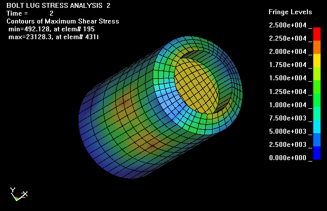
Here the bolt lug has been removed so the shear stresses can be viewed at the
base of the bolt lugs. Dan Lilja assumes, in his analysis, that the shear
stresses are uniform over the area of the bolt body to lug. Assuming a uniform
shear is necessary for a simple stress calculation and gives reasonable results.
However with the more detailed calculation, the shear stress are shown to have a
maximum near the base of the lugs and decreases to as little as fifth of maximum
near the forward end of the bolt. The use of the LS-DYNA code allows one to view
and understand more clearly the complicated stress and deflection conditions
that structures undergo when resisting service loading.
WHAT IS EFFECTIVE STRESS?.... Here is some information on Effective Stress or often referred to as Von Mises Stress. In structures under load, the stress state is not a simple uniaxial state of stress but a more complex triaxial state of stress. Plastic deformations (also called plastic flow) will occur in a material when the effective stress, seff exceeds the uniaxial yield stress. Here is the equation for the effective stress when a triaxial state of stress exists and s1, s2, and s3 are the principal stresses in the three orthogonal directions. The effective strain is eeff.
seff= (2½/2) [(s1s2)2+ (s2s3)2+ (s3s1)2]½
eeff= (2½/3) [(e1e2)2+ (e2e3)2+ (e3e1)2]½
1. When all three orthogonal stresses are equal (hydrostatic stress
state), the effective stress is zero. There is no yielding.
2. When s2
and s3
are zero, then the effective stress is the uniaxial stress. This is the stress
condition of an axial pull test specimen.
Looking at the equation, one can see some interesting concepts. If there is no
tension, but sufficient biaxial compression in the other two directions, then
there could be axial yielding in extension in the third direction. (This is like
squeezing a cylinder of putty in your hand and having it squirt out each end).
WHEN YIELDING OCCURS.... One can visualize yielding as a cylinder in 3-D space. The axis of the cylinder is the line of the hydrostat. It is a line where s1= s2= s3. When the triaxial stress state deviates from the hydrostat line but stays within the cylinder, there is no yielding. When the triaxial stress state deviates from the hydrostat outside of the cylinder then yielding occurs.
NO YIELDING IN HYDROSTATIC COMPRESSION.... When a metal is in
hydrostatic compression (immersed in a fluid and the pressure increased), there
is no yielding, no matter how high the pressure. With a real material, micro
voids would be closed and at extremely high pressures, the crystal
structure could be changed, such as converting carbon to a diamond. These
pressures are beyond those normally considered in engineering analysis of the
strength of structures.
NO YIELDING IN HYDROSTATIC TENSION.... When a metal is in hydrostatic
tension, in theory, there is no yielding. I can't think of any realistic way to
apply extremely high hydrostatic tensions. The limiting point would be the bond
strength of the atoms in the crystals.
Finally... The rifle bolt and lugs are in a complicated triaxial stress state at
each location and the FEA codes determine this for each tiny element. The
back-of-the-envelope p/a type calculations are of little value in accurately
predicting and understanding what is happening during loading such structures
where a triaxial state of stress exists.
Good Hunting... from Varmint Al
For the serious reader: How to
Check Another Engineer's Calculation.![]()
Last Updated: 02/08/2013
End of Page![]()